A General-Purpose USB Control Panel
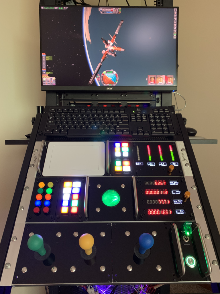
The KontrolRack is a proposed standard that consists of a main vertical Chassis, a horizontal Frame, and customizable Modules. Modules hold devices such as buttons, joysticks, and displays. Bi-directional Modules can include WiFi AP with a configuration page.
Supporting Repositories
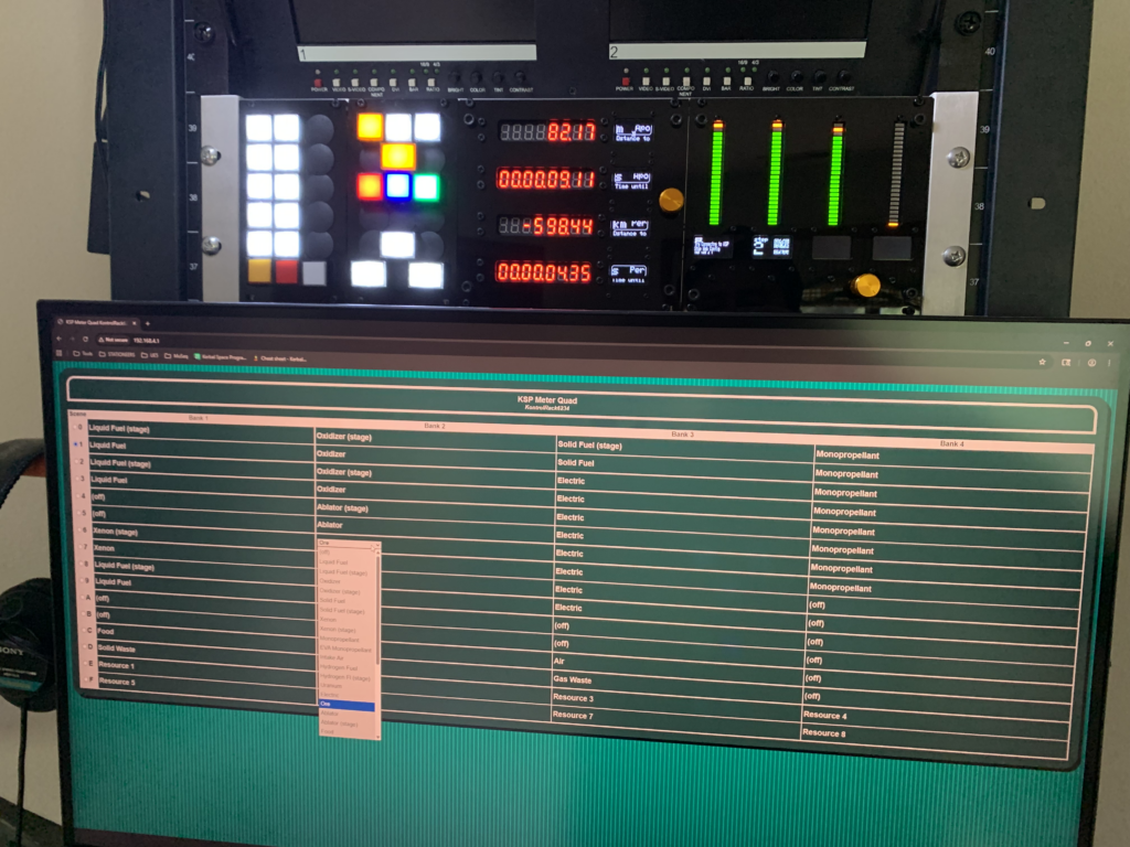
- https://github.com/gogodyne/KontrolRackLib
An Arduino-compatible firmware library, with examples for KSP/KSP2. - https://github.com/gogodyne/KontrolRackPanel
Templates for designing custom faceplates and backplates.
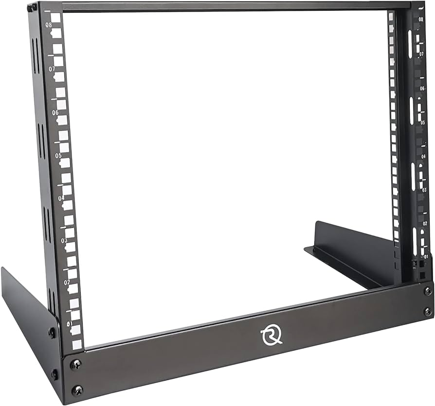
Chassis: 19-Inch Rack
A standard 19-Inch Rack consists of two vertical rails with mounting holes.
A Rack is measured in vertical units, such as 3U.
Objects mount to a Rack with Ears that bolt to the rails.
Frame: Eurorack
A rackmount Eurorack consists of a pair of horizontal Rails mounted to 3U Rack Ears.
The Rails are fitted with either threaded holes or sliding nuts, sized for M3 bolts.
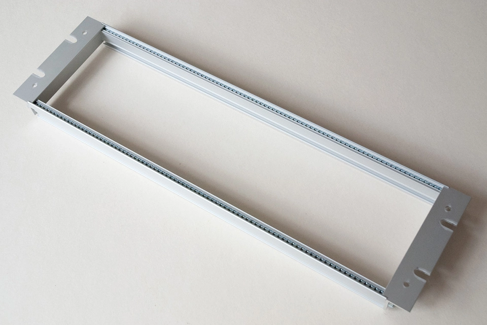
The Eurorack Frame is measured in horizontal units called HP, for “horizontal pitch”.
A Eurorack Frame that fits a 19-Inch Rack is 84HP wide.
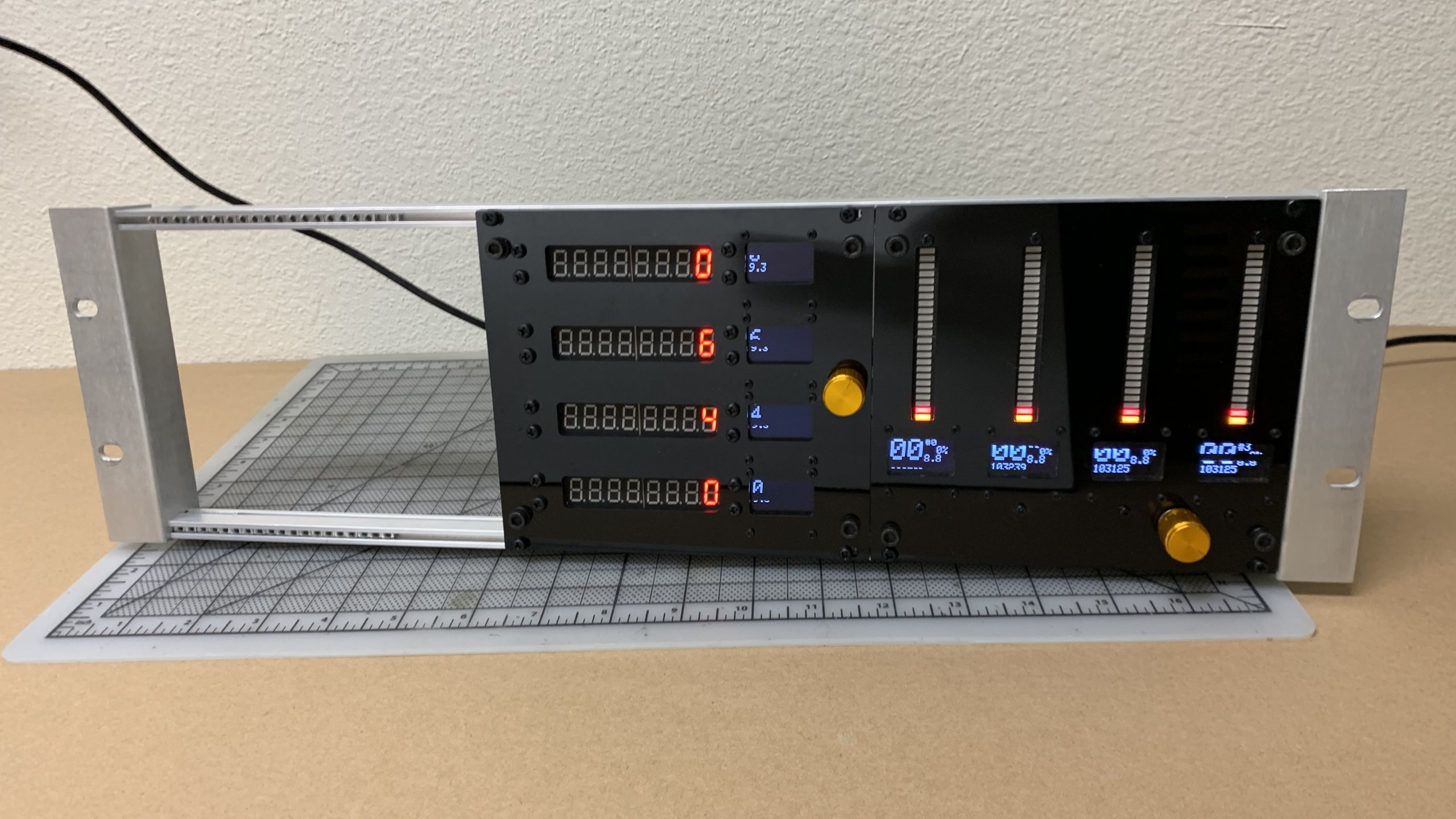
Module
A Module consists of a Faceplate and an optional Backplate.
A Module has one of three widths: 14HP, 28HP, and 42HP, which correspond to ⅙, ⅓, and ½ of the full 84HP width of the Eurorack Frame.
A Module mounts to its Frame at the four corners of the Faceplate.
The Eurorack Rail bolt size is M3 x 6mm or longer, depending on the Faceplate thickness. Nylon bolts are best against acrylic Faceplates.
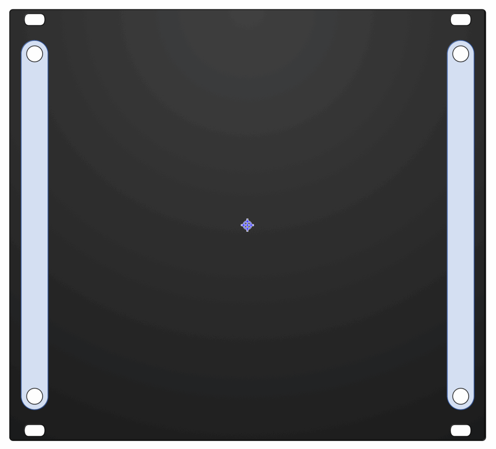
Faceplate
A Faceplate has standard Eurorack dimensions, with 4 mounting holes.
Each Faceplate is custom-designed for the devices that will mount to it.
Devices must be vertically inset from the mounting holes to accommodate the Eurorack rails, and horizontally inset to accommodate the Guardrails.
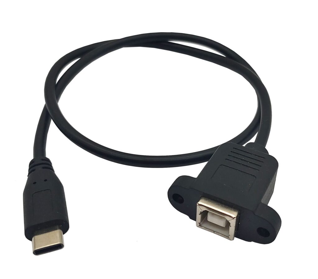
Interconnect
Each device in a Module can need at least 2 wires that must connect to a microcontroller. Sometimes a Module will need other connections such as a USB port or a dedicated power source.
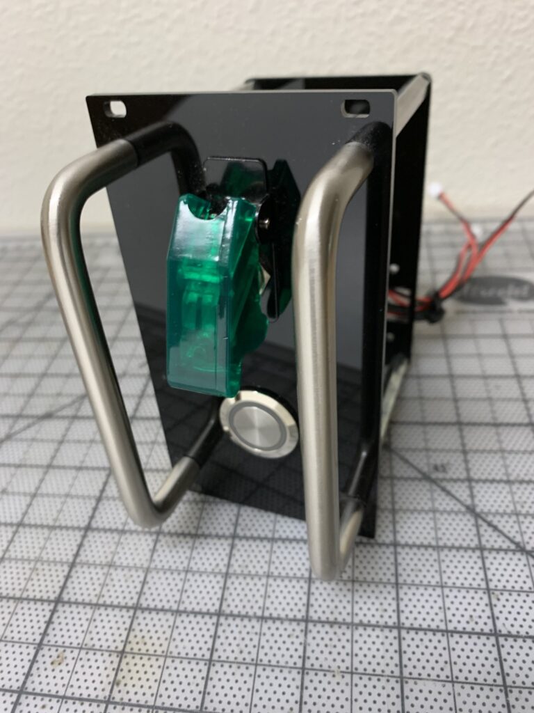
Backplate
An optional Backplate is fitted to its Faceplate’s Guardrail holes, and is smaller than the Faceplate.
Connector ports can be mounted to a Module’s Backplate.
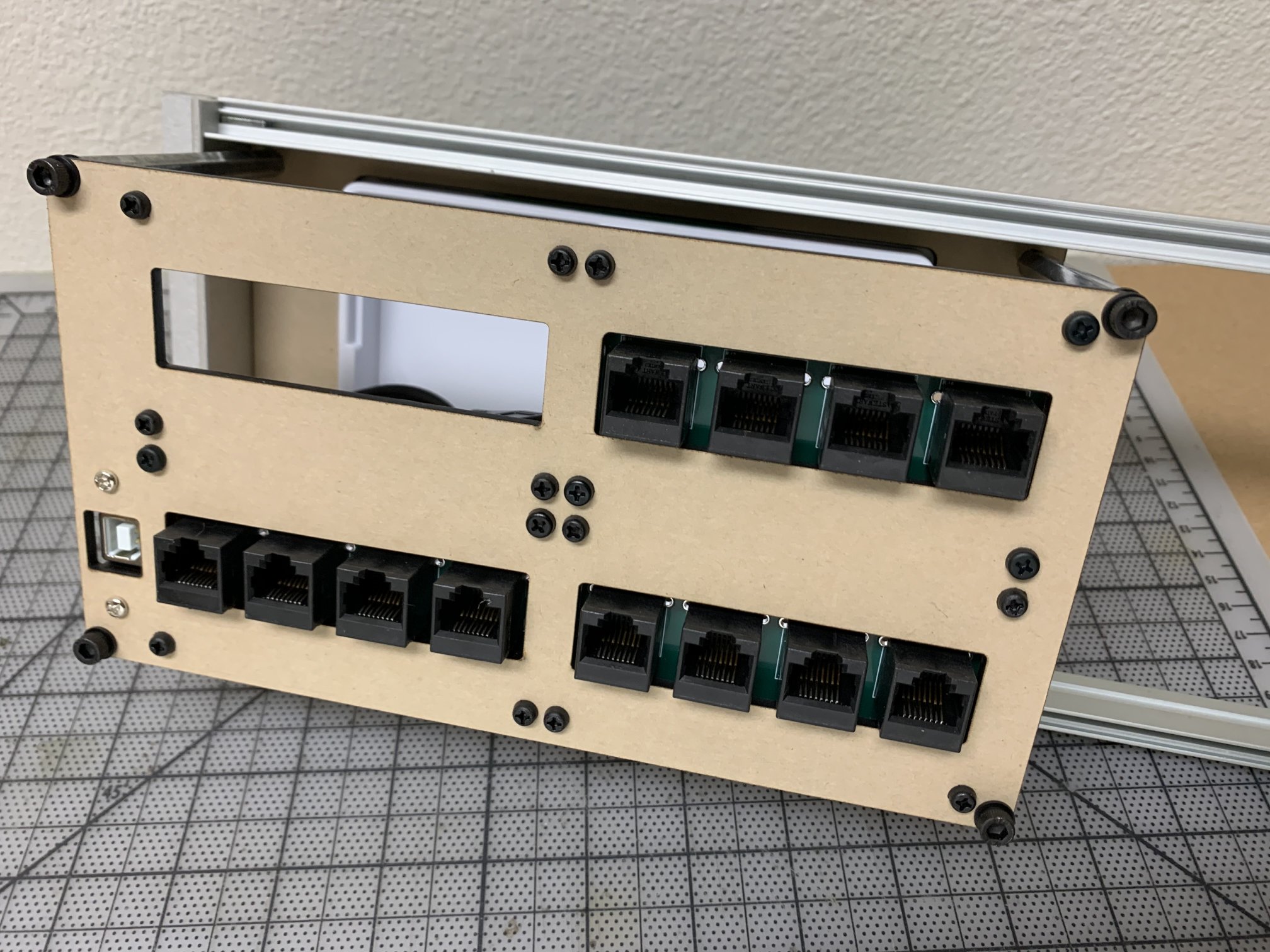
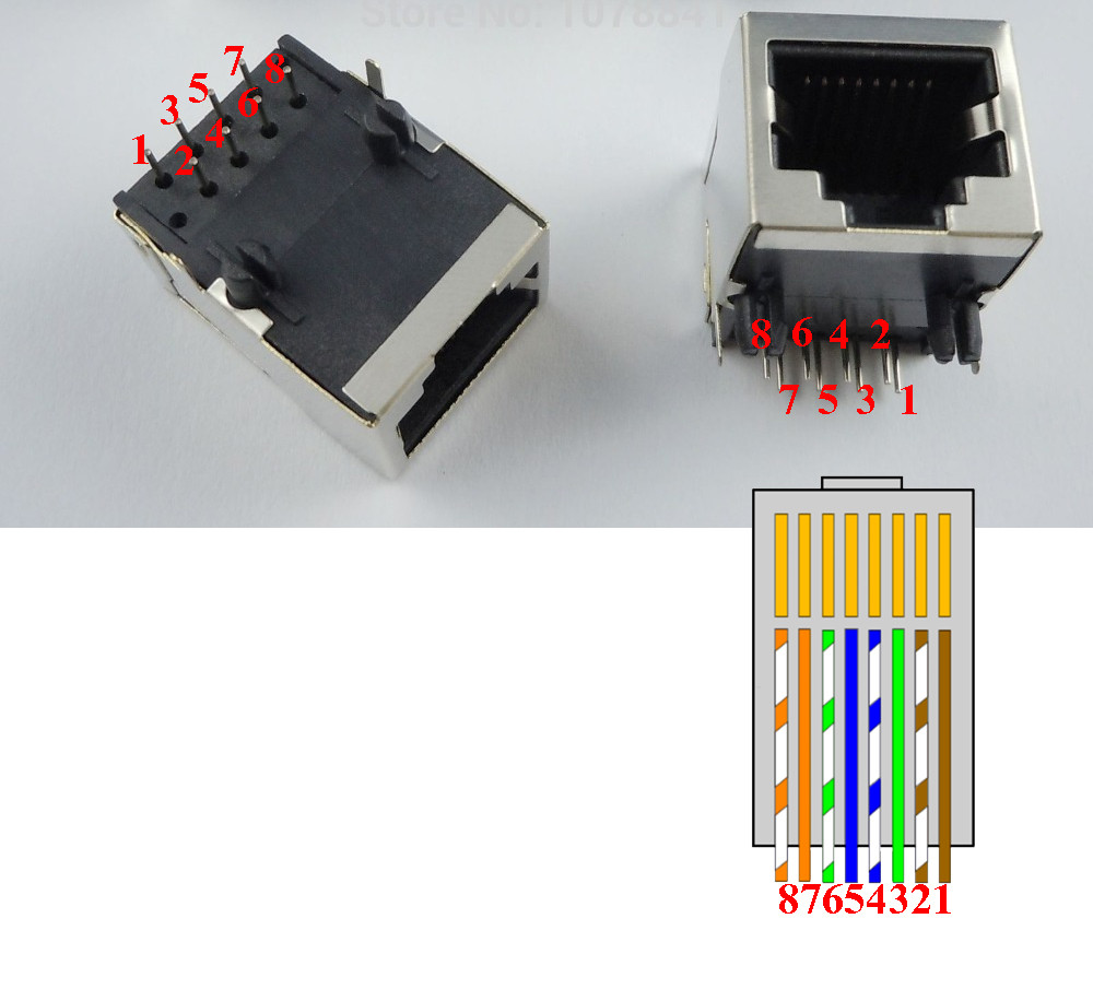
RJ45 + JST-XH 2.54mm 2P
An RJ45 jack connects to a Cat5 network cable that features 4 pairs of wires. Network cables are common and available in many lengths and colors.
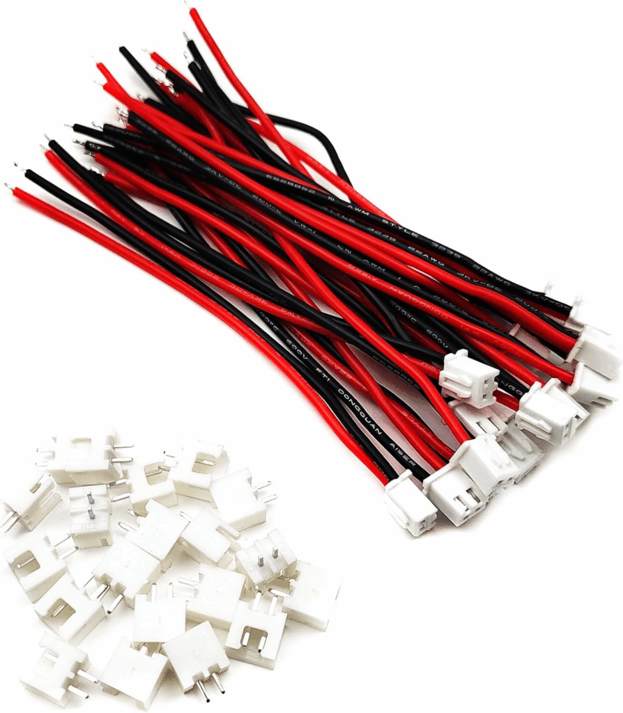
Industrial 16mm pushbuttons and arcade-style buttons use spade connectors. Standard JST-XH 2-pin cables have snap-in housings, and are available with spade ends.
JST-to-RJ45 Breakout
A custom breakout board can connect lines from the RJ45 jack in 4 pairs to 4 JST-XH connector jacks. This allows for the use of inexpensive, reliable, and easily organized Cat5 cables between Modules.
A breakout board can also provide power distribution using a power and ground plane.
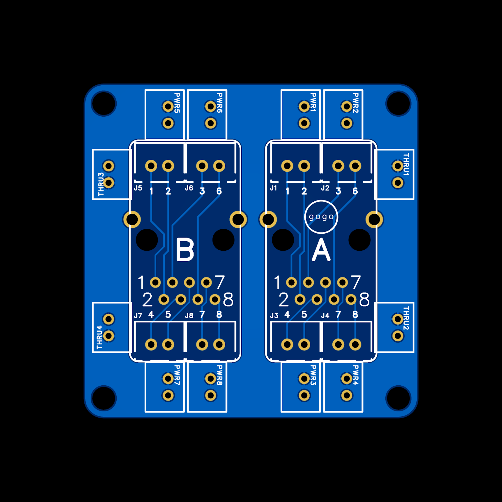
Schematics for 1, 2, 3, or 4 jacks can be found at: