Input
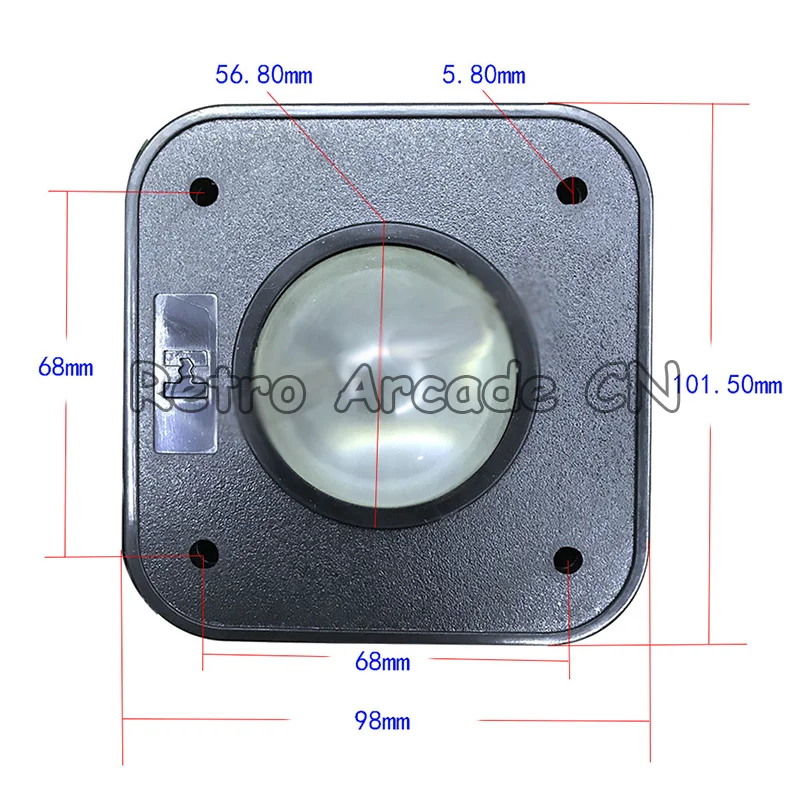
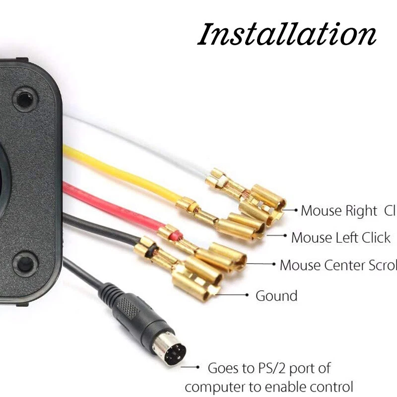
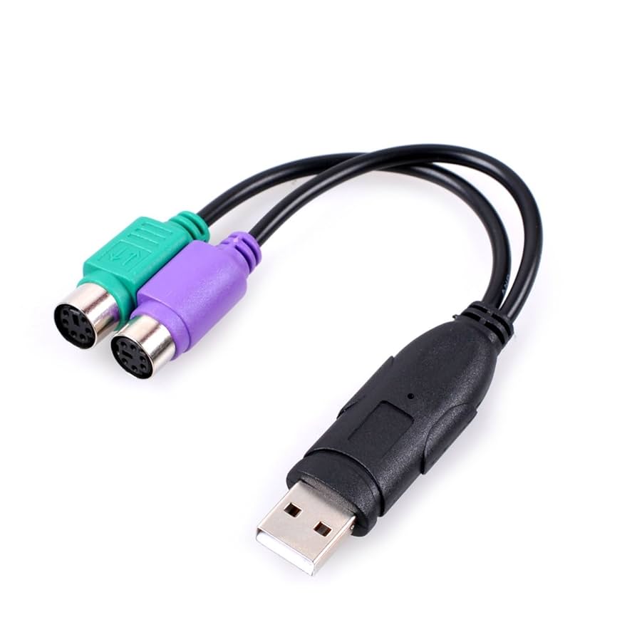
Trackball, Arcade (PS/2)
This type of trackball is equivalent to a mouse, and durable enough for industrial environments. This device can be interfaced with a microcontroller, or directly to a computer that supports PS/2, or USB using an adapter.
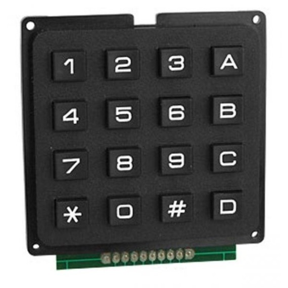
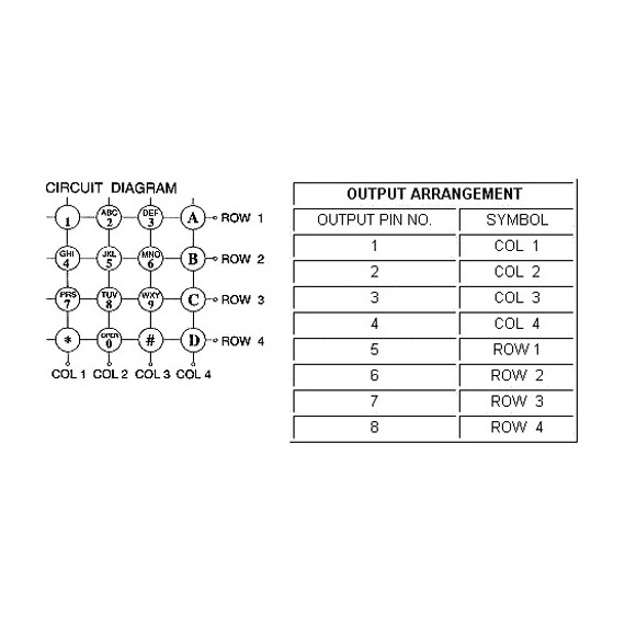
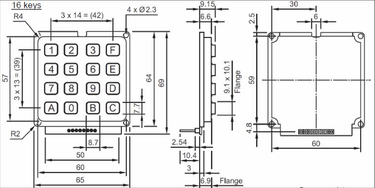
Keypad, Matrix 4×4
A button matrix is designed to use fewer IO pins than the number of buttons that it tracks. For example, a 4×4 matrix requires 8 digital IO pins on the microcontroller.
To read a button matrix, a microcontroller requires a number of digital IO pins (DIO) equal to the number of rows times the number of columns (required pins = Rows x Columns).
Joystick
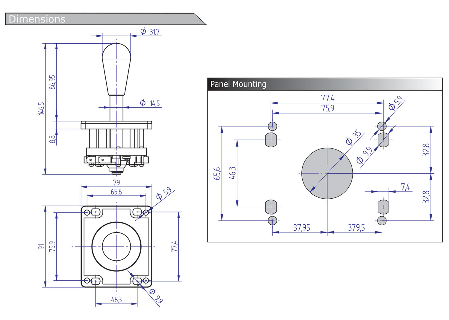
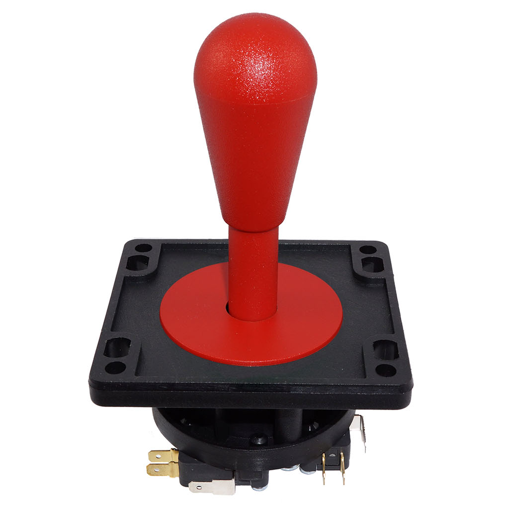
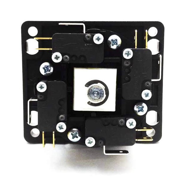
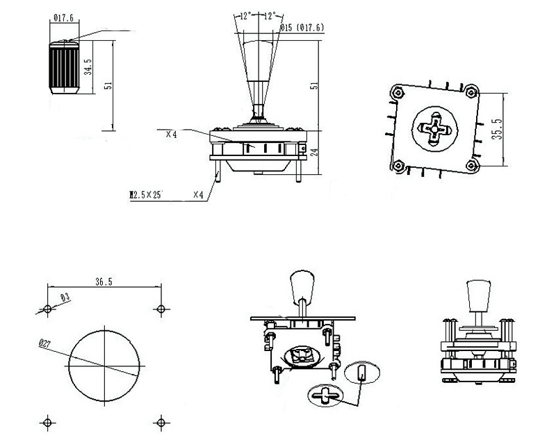
Digital Joystick
A digital joystick has 4 switches. Each switch can be closed simultaneously with one of its neighbors, totaling 8 discreet directions.
A microcontroller requires a digital IO pin (DIO) for each switch.
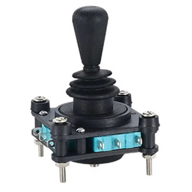
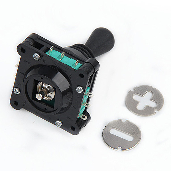
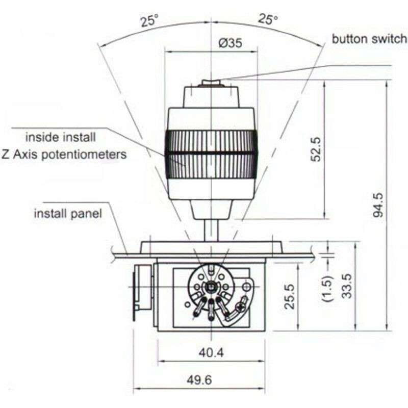
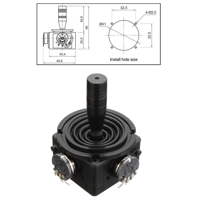
Analog Joystick
An analog joystick has one or more potentiometers, usually spring-loaded to center. Two terminals supply the voltage, and the third terminal is the “wiper” which reads the amount of voltage resulting from the variable resistance. When the stick is in the middle position, the voltage at the “wiper” is 50%, while full deflection to either side results in either 0% or 100% voltage. Swapping the polarity of the power leads reverses the resulting reading at the “wiper”.
A microcontroller requires an analog input pin (ADC) to read each potentiometer value.
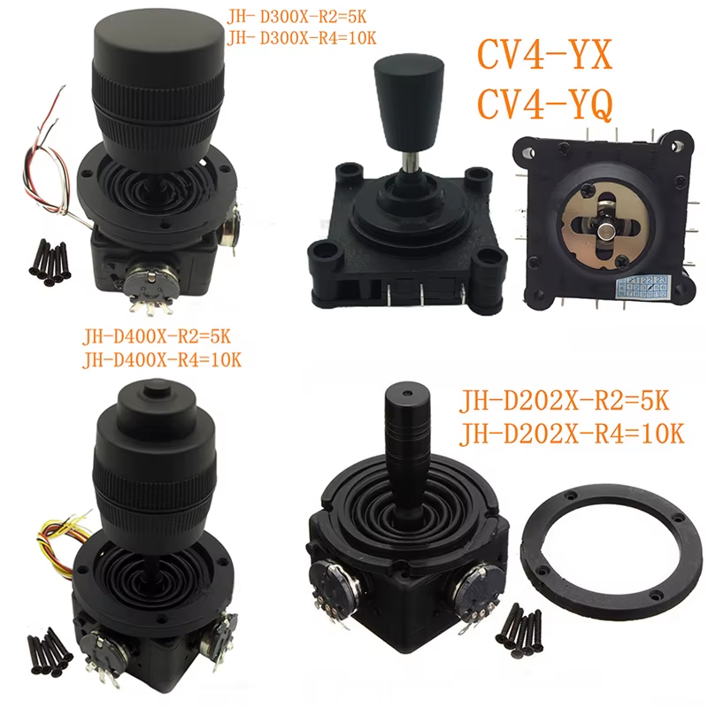
JH-D202X-R4 (2-axis, 10k)
JH-D300X-R4 (3-axis, 10k)
JH-D400X-R4 (4-axis, 10k)
Input/Output
A pushbutton is a spring-loaded switch which operates by closing and opening a circuit. Typically, a switch is “closed” when pressed.
There are two ways that a switch can behave after being pressed:
- Momentary (MOM): The switch will return to the previous state.
- Latching (LATCH): The switch will remain at the new state.
A microcontroller requires a digital IO pin (DIO) to read the state of a pushbutton.
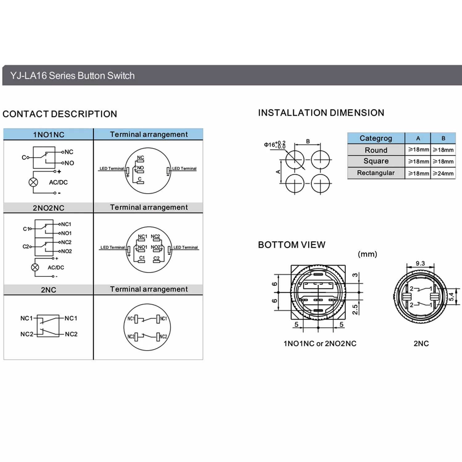
Some switches have terminals to detect specific states of the switch:
- NO = Normally Open: the circuit is open when the switch is not pressed.
- NC = Normally Closed: the circuit is closed when the switch is not pressed.
- COM = Common: this is the terminal that all the circuits connect to, and is typically wired to GROUND.
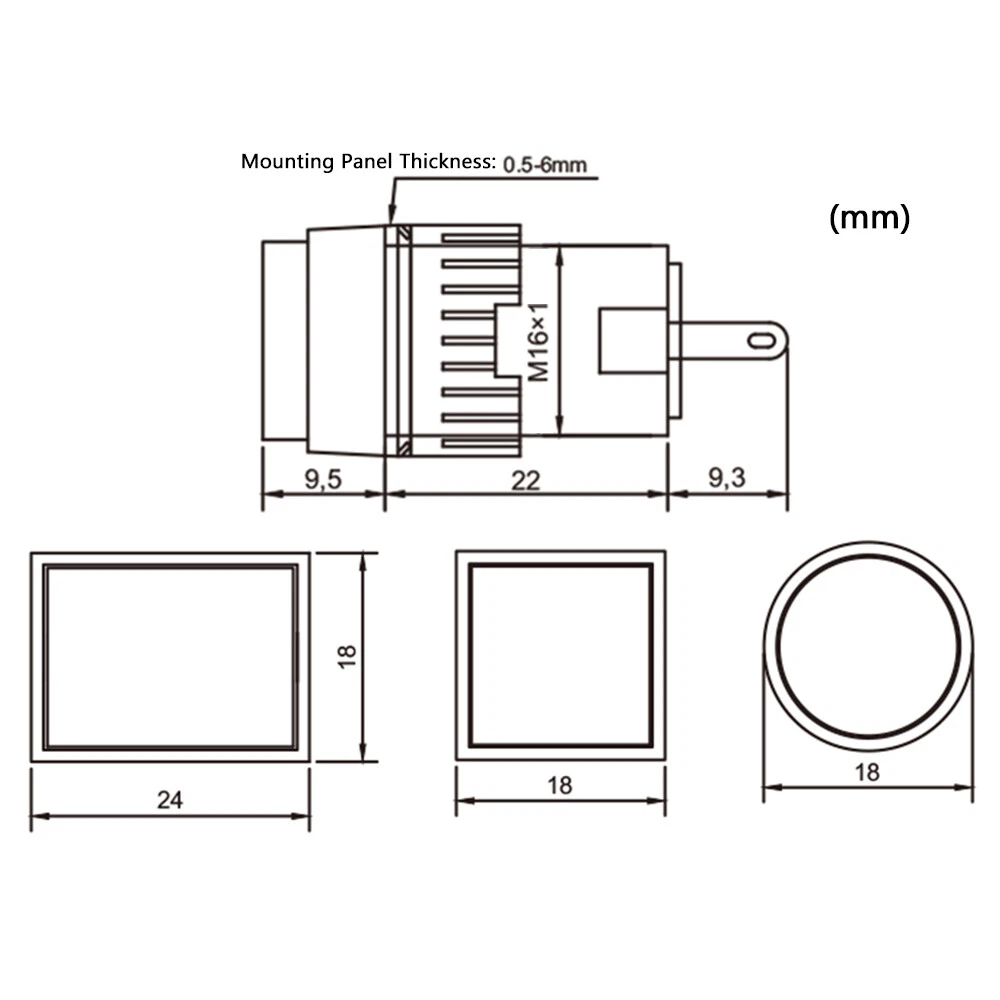
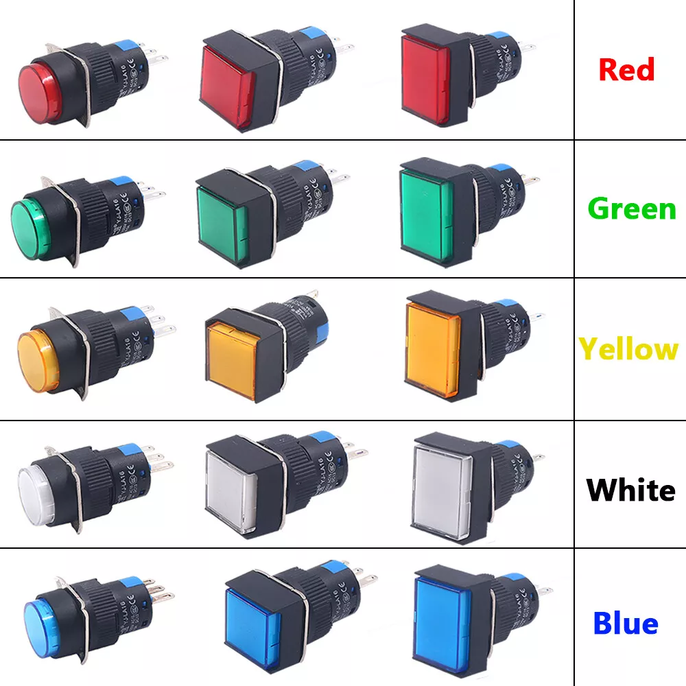
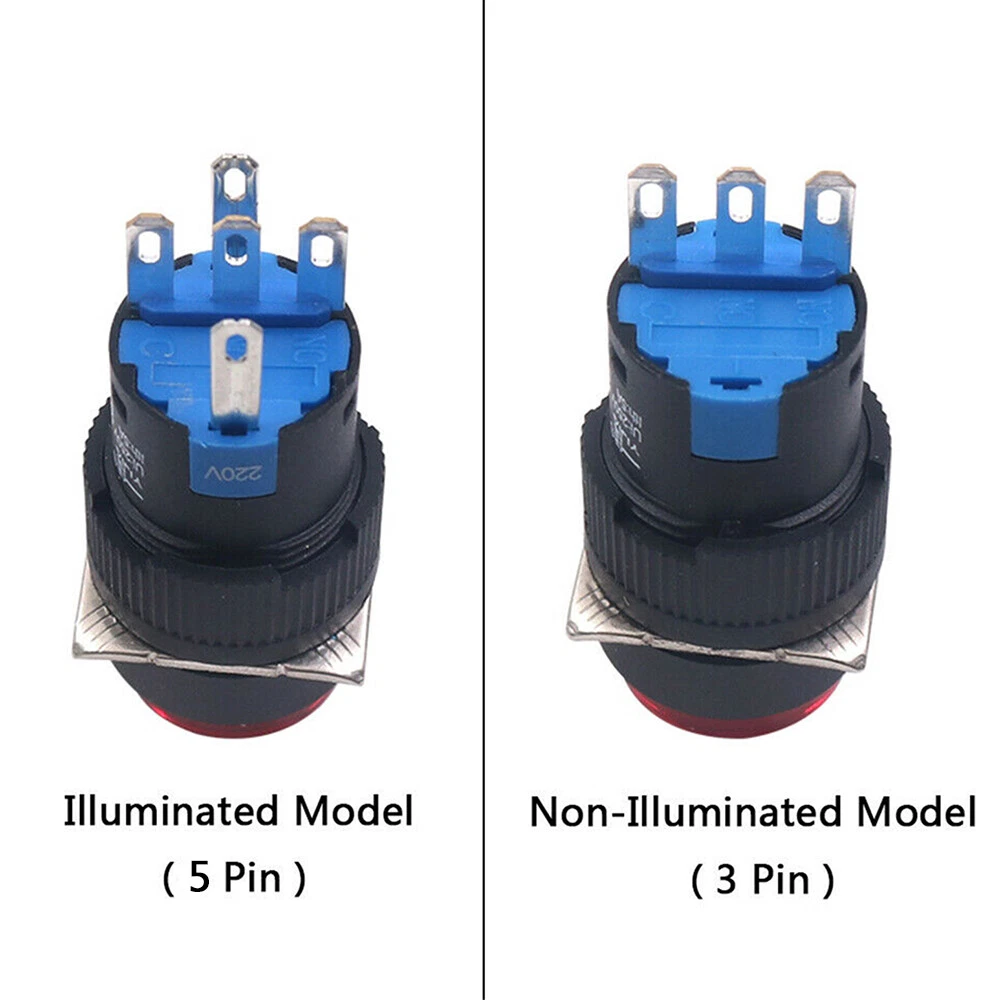
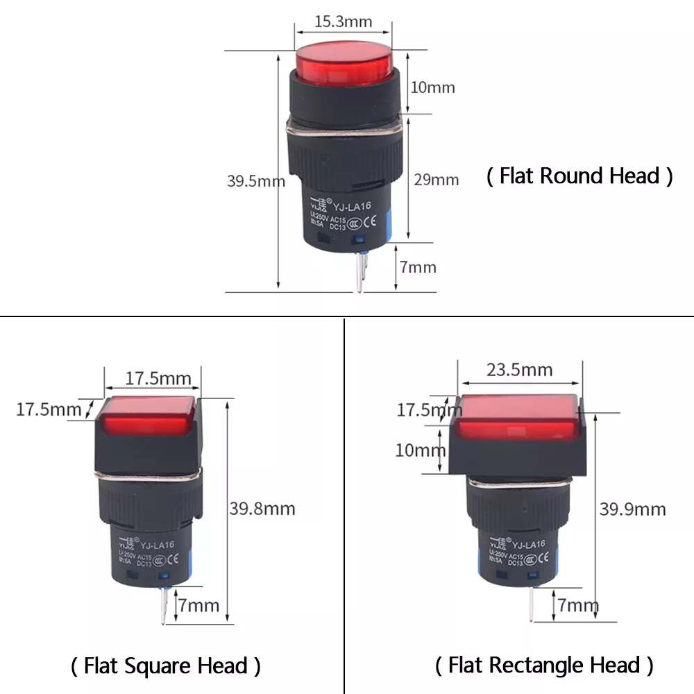
Pushbutton LED A6 16mm
The A6 series pushbutton is an industrial device that is manufactured in several shapes, sizes, and colors. It can include an LED, with its own internal current-limiting resistor, meaning that its terminals can be connected directly to voltage. The button is labelled for a maximum voltage, with typical ratings ranging from 5V to 220V. Supplying less voltage than the maximum will produce a dimmer light.
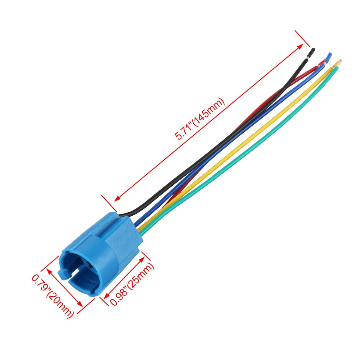
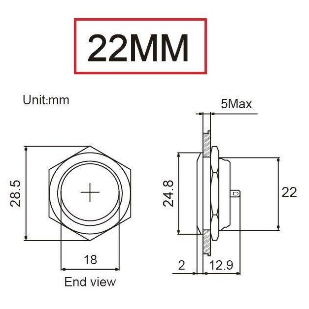
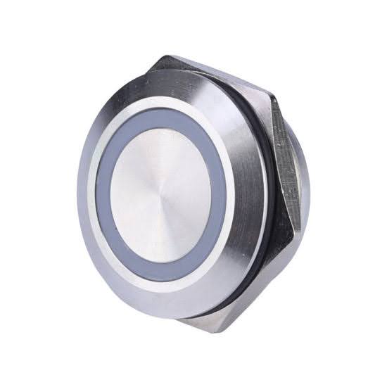
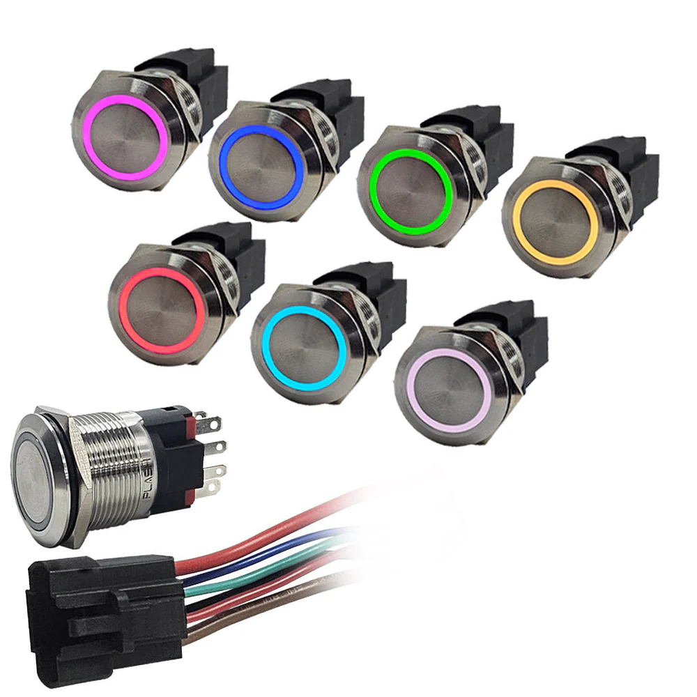
Pushbutton LED Metal 22mm
A metal pushbutton is sleek and durable. It can include an LED with its own internal current-limiting resistor, so voltage can be applied directly to the terminals. A button with an internal LED is labeled for its maximum voltage. A voltage applied below the maximum will produce a dimmer light.
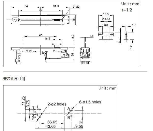
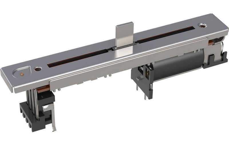
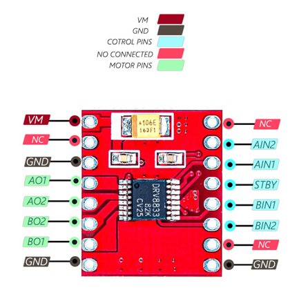
Fader Motorized 60mm
A motorized fader is a combination of a slide potentiometer, a touch sensor, and a motor. Typical slide faders are 100mm, but can be found at 60mm.
A microcontroller requires an analog input pin (ADC) to read the potentiometer value.
A microcontroller requires an analog input pin (ADC) to read the touch sensor.
Basic Motorized Fader operation:
- The microcontroller reads the potentiometer value and operates the motor to change the slide position, up or down, until the desired value is reached.
- The touch sensor is used by the microcontroller to disable the motor while the user is operating the slide.
Output
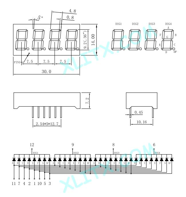
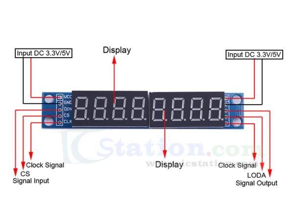
Numeric 7-segment 8-digit MAX7219
These LED segment devices require only 3 digital IO (DIO) microcontroller pins to operate, and can be chained.
I2C
https://en.wikipedia.org/wiki/I%C2%B2C
The I2C protocol is a serial communication standard. The wiring is only two wires for data, plus two wires for power. It is a “bus”, which allows for multiple devices to be connected to the same communication lines. In order for specific devices to be targeted, each must have a unique I2C address on the bus.
Most I2C devices will have a default address, configurable within a range of addresses. Some devices will have addresses that are the same, or their ranges might overlap. These devices must either be reconfigured to be unique, or wired to separate buses. Some configurations require soldering, while others use jumpers.
If all devices are on the same bus, only two data pins on the microcontroller are used, thus freeing more pins for other uses. Some microcontroller can support multiple I2C buses.
Useful I2C devices include:
- I/O Expander: These devices have their own IO pins that are made available to a microcontroller through I2C, effectively increasing the total number of data pins. Expanders can be either digital or analog.
- Display: Any number of displays can be controlled through an I2C bus.
- I2C Switch (MUX): An I2C switch (or multiplexer) can be used to isolate devices onto their own buses, or “channels”. This allows a microcontroller to communicate with only certain devices at any given time. Devices can have the same address if they are on separate channels. Chaining I2C switches with each other will increase the number of devices available to a microcontroller.
Expander 8Ch Digital PCF8574
0x20-0x27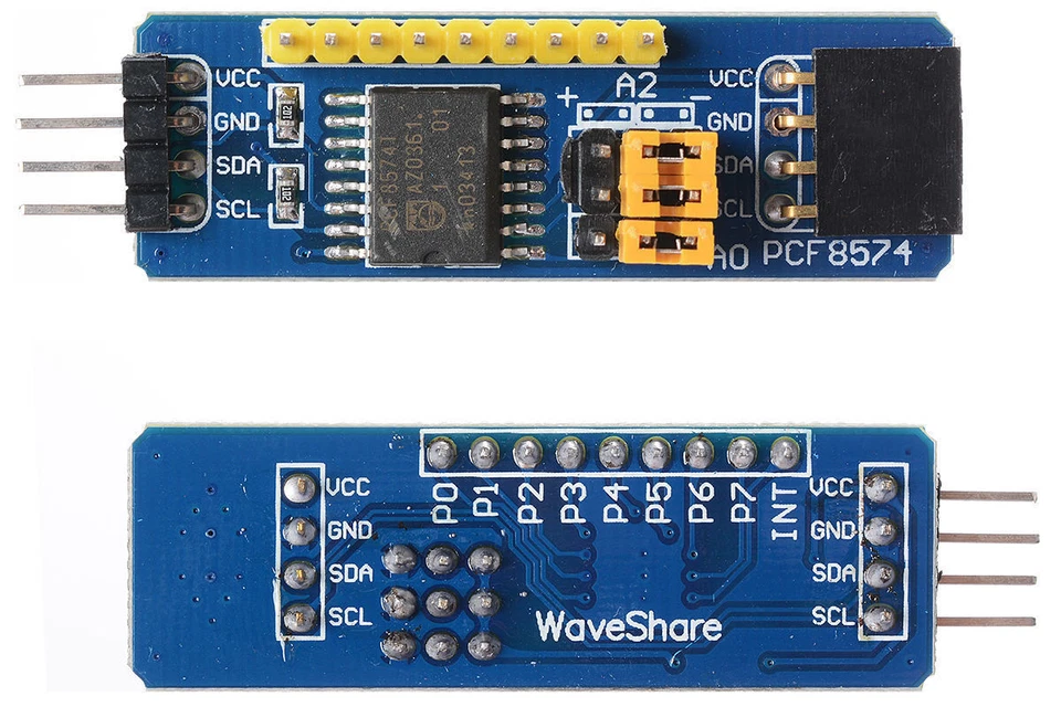
Expander 16Ch Digital PCF8575
0x20-0x27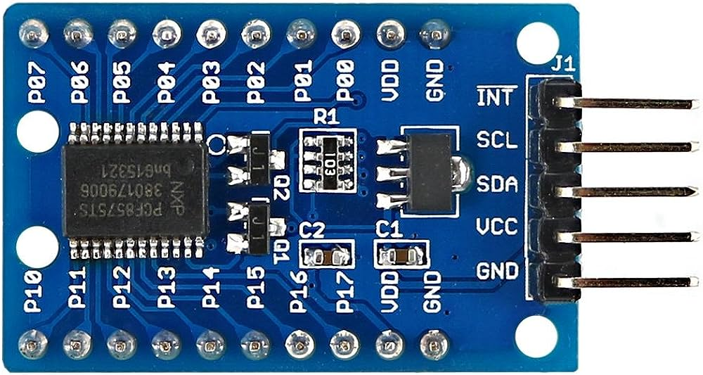
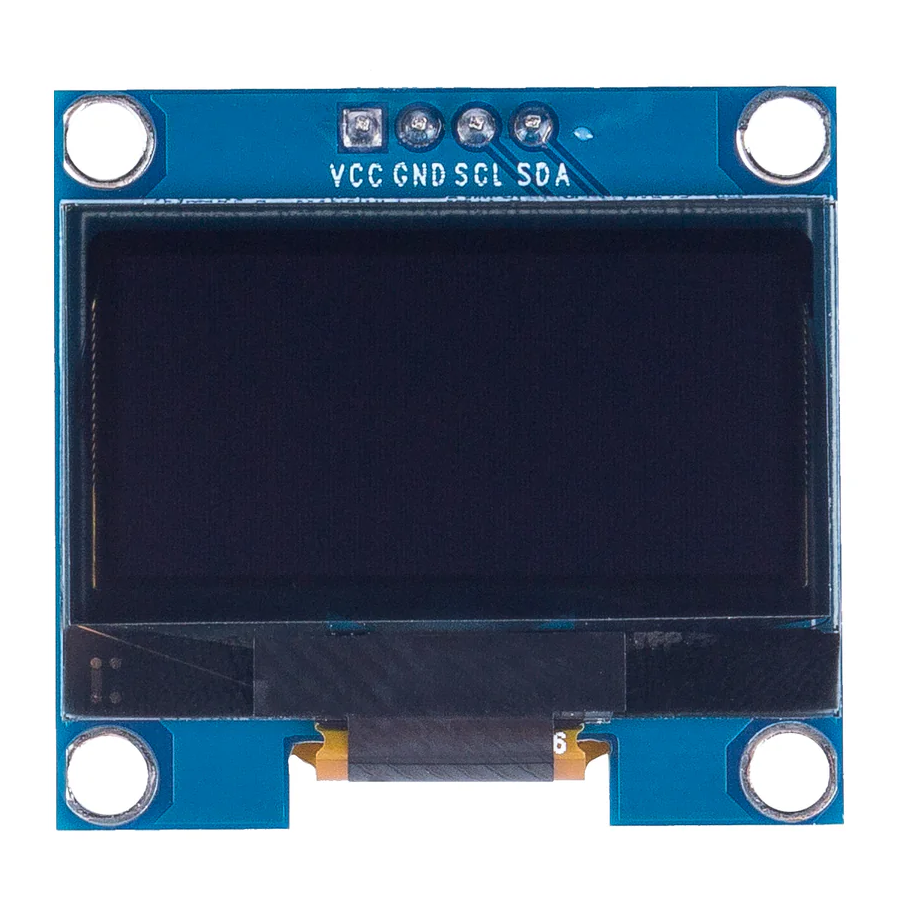
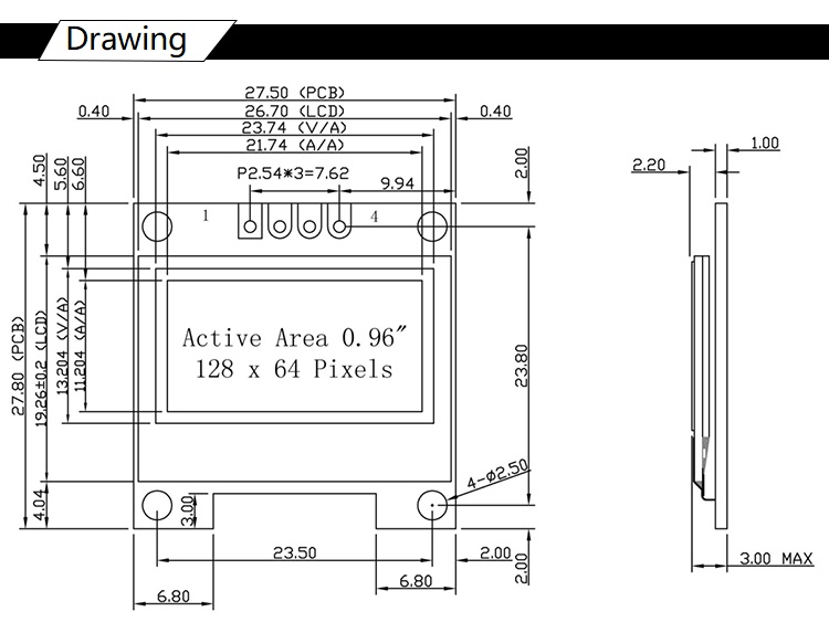
OLED SSD1306
0x3c,0x3D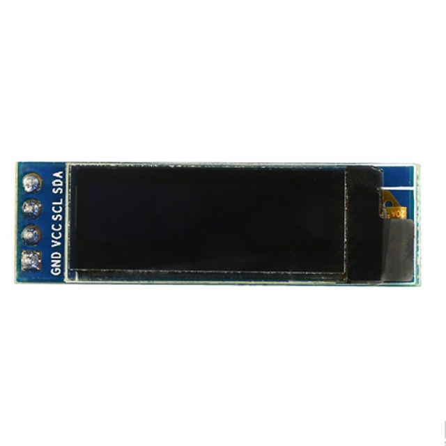
I2C MUX 8Ch TCA9548A
0x70-0x77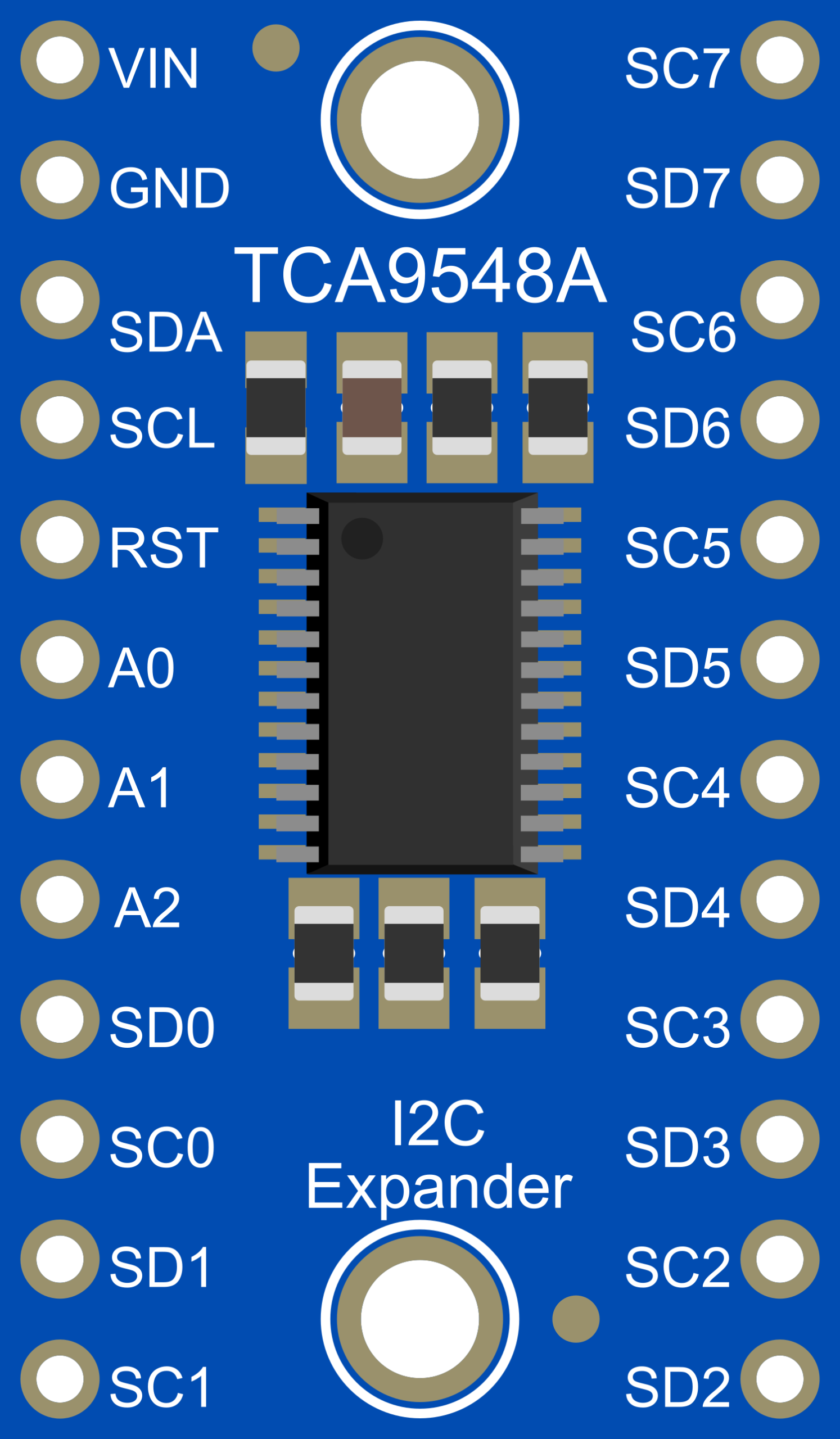
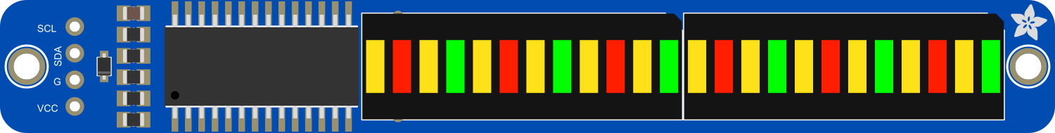
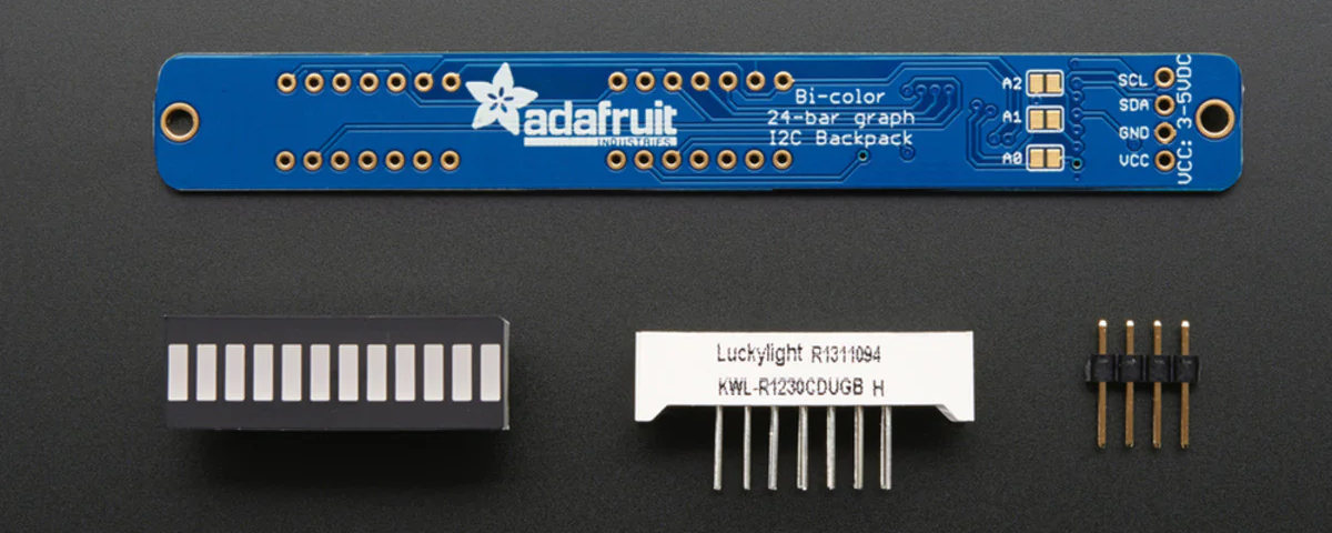
Adafruit 24-Segment Bargraph
0x70-0x77